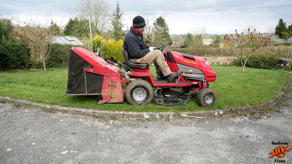
I had a call from the owner of a Countax C300H – “…the Countax blades won’t engage.” The story went on to reveal the classic intermittent fault, where sometimes they would work fine and other times they wouldn’t turn on. I found the diagnosis and repair quite satisfying so I thought I’d write about it.
The blades are driven by a belt and pulley connected to the engine crankshaft via an electromagnetic clutch. This enables electronic control of the blades along with all the necessary safety cut offs.

Working out why the Countax blades won’t engage
What could it be?
Thinking through the potential causes, this could be a problem with:
- Electromagnetic clutch.
- Wiring.
- Safety cut off system (e.g. seat sensor).
- Circuit board.
- Blade drive switch.
I decided to start at the blade drive clutch and work backwards. Why? Well the blade clutch and its wiring are underneath the tractor, amongst all the grass, twigs etc, so I thought they were the most susceptible to damage.
Visual inspection
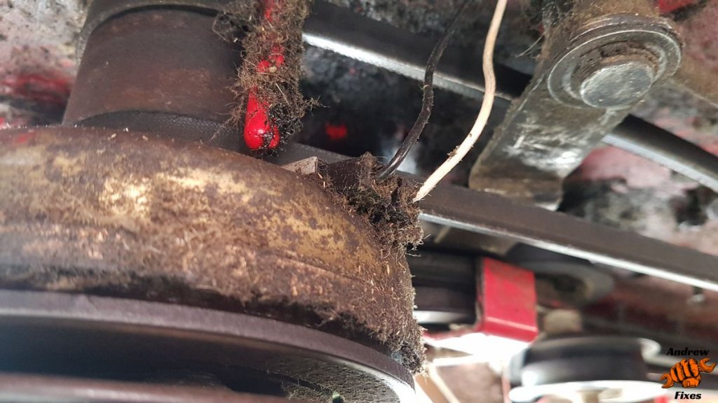
I like to start by having a good look round things. The clutch was caked in grass, as were the 2 wires going to it. Despite this it all looked intact.

Next I checked the wiring to the safety cut off switch under the seat. This is designed to stop the blades spinning if the driver gets off the seat. This also looked fine and the switch seemed to be working.
You might be wondering about fuses. There are only 2 on this tractor, one for the charging circuit and one for the ignition, lights and safety mechanisms. If a fuse had blown, we’d expect to see more problems than just the blade drive.
Checking the voltage
With no obviously loose wires at the blade clutch end, I decided to measure the voltage across the 2 wires, at the connectors to the clutch. With the ignition on, but the engine not running, the blade switch can be moved to the ‘on’ position and if all is well, you can hear the click of the electromagnetic clutch engaging.
If you wanted, you could further verify this by applying battery voltage directly to the clutch and listening for it engaging.
The voltage was all over the place, as we might expect for an intermittent fault.
More wiring checks
Having found this variable voltage, I traced the wires all the way back to the control board, giving them a good wiggle as I went, to see if I could influence the voltage reading at the clutch. When I got to the circuit board behind the ‘dashboard’ I did start to see some relationship between my wiggling and the voltage changing.

Inspecting the circuit board and connector
I felt I was onto something so had a close look at the circuit board and connector. I found that the white wire at the far end of the connector was under more tension than was ideal. This had caused it to come loose in the connector.
BUT…that was not the only problem. There was also a dry solder joint where the connector socket was soldered to the circuit board. Repairing the wire may have improved things, but it wouldn’t completely fix the problem.

Fixing the cause of the Countax blades not turning on
Refitting the wire to the connector
As you’ll see from the picture, the connector is a ‘punch down’ type, where each wire is pushed down into the connector and metal contacts cut through the insulation to make contact with the copper inside. Unfortunately it wasn’t quite as simple as just punching the wire down again. The end of the wire was somewhat corroded, so that section needed cutting off. This would make the wire too short to reach the connector.
I chopped out the corroded section of the wire and soldered in a new (and slightly longer) piece. This enabled me to make a new joint into the circuit board connector.
Resoldering the dry PCB connection
This was quite a simple process. I just fired up my soldering iron and resoldered the dry joint on the circuit board.
Have these repairs fixed the Countax blade drive problem?
Yes they have! I tested it again without the engine running first. The voltage at the blade clutch was much more stable and much closer to battery voltage. More importantly, there was a reassuring and reproducible clunk from the electromagnetic clutch with each operation of the blade drive switch.
Next I put everything back together and tested it again for real. All was well, with the blades engaging first time, every time. And no cutting out whilst mowing, as there had been before the repair.
All in all this was a very satisfying repair, with the only costs being some solder and a ~5 cm piece of wire. I hope it helps if your Countax blades won’t engage!
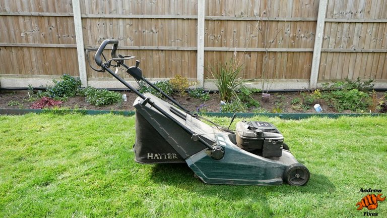
I’ve also written about servicing one of these tractors, and replacing the grass collector brushes.


Hi Andrew,
I have your Countax YouTube videos saved to my private Countax playlist, and have found them very useful. Thank you for taking the time to create such detailed information , and share it with Countax owners around the world.
I’m in Melbourne Australia, and I don’t think there are a lot of Countax mowers around here, though occasionally they appear on marketplace which is where mine came from.
Full disclosure, I have never tried to contact Countax for assistance, and perhaps I should have, but in the back of my mind, I feel like they are (or were) in the business of sales, and will only try to sell me something that will then make my bargain purchase not so much of a bargain anymore.
In any case, the saying goes… “Give a man a fish, feed him for a day. Teach a man to fish, feed him for life.”
So, if my Countax breaks down, I need to fix it myself.
I have a Countax Lawnmaster C series… I think it’s a 2000 model C300H due to the Briggs & Stratton INTEK OHV engine, IBS 92cm/36”, and it looks the same as the image on the front of the owners handbook. As in the same cutting deck with the black pulley cover, the location of the deck height adjustment leaver and PTO engagement lever.
However, my engine is a 13.5hp, so that doesn’t correlate… and I haven’t been able to 100% identify the serial number (SN: 00918 3B806 0017 [C]).
My mower looks like it has been to war and back, a few times over, and that I’m not it’s only owner who wants to do their own repairs. It looks to have had the starter solenoid already replaced, with the old one still sitting behind it with some random wires hanging out of it. There are multiple earth wires running to the battery with many layers of electrical tape bandages.
I removed the cutting deck shortly after purchase due to a bearing explosion because of its never in its lifetime greasing routine and consequently melting in the spindle housing (note to anyone new to ride on mowers, they are not supposed to be really really loud).
While I have cleaned up all the housings and purchased new bearings, I am still yet to reassemble said components. I’m thinking of adding grease zerks for easier maintenance.
My more recent issue is with the PCB board. It started with a blown fuse, and resulted in a fried resistor. Part number for the PCB board is 448001803.
I have has someone look at the board with me, and I know how to go about replacing the resistor, and tracing the track to the loom. I’m just wondering, if you might have any knowledge of what resistors are on this PCB board? I believe it’s on track 5.
Due to the board not being in a PCB board box for many years, it’s a bit discoloured. So even after cleaning all the layers of dirt and grime that made its way inside the unsecured ziplock bag it was housed in, I’m not 100% confident we have identified the correct colours of the bands. And I don’t seem to be able to find a clear picture online, or a schematic of the actual board components to cross reference.
Any assistance you might be able to offer would be greatly appreciated.
Thanks for your time in reading my novel…
Hi Tanya
I’ve emailed with a link to the best picture I can find. Hopefully you can identify the resistors from that.
Thank you
Andrew